Creating an AutoCAD drawing of a cone crusher requires a precise blend of technical acumen and an understanding of engineering principles. Whether you’re a seasoned professional or a novice in the realm of industrial design, mastering this skill can significantly enhance your efficiency and output quality. At Sbm, we specialize in providing high-performance crushers, mills, and other heavy industrial equipment. Our products facilitate streamlined processes and deliver robust results, essential for any engineering project, including AutoCAD drawing creation.
AutoCAD is a versatile and powerful software application used extensively for creating detailed 2D and 3D drawings. For designing a cone crusher, it’s crucial to start with a solid grasp of the fundamental concepts of AutoCAD. These include understanding the workspace, layers, and the basic drawing tools that you will be employing throughout your design process. A thorough understanding of these concepts allows you to create precise and detailed drawings tailored to your project requirements.
Before delving into the actual drawing, one must have a clear conceptual understanding of the cone crusher itself. A cone crusher is a vital piece of equipment in the mining and aggregate industries, used for crushing various materials into smaller, finer aggregates. Knowing the components and their functional relationships within the crusher is essential. This includes parts like the crushing cone, the shaft, the mantle, and the various liners and frames that provide structural stability to the machinery.
At Sbm, we offer a comprehensive range of cone crushers, specifically designed to meet varying operational needs. Our crushers show outstanding performance, reliability, and longevity. Familiarizing yourself with these products will enhance your ability to create detailed and accurate AutoCAD drawings, as you will understand the specific features and functionalities to incorporate into your design.
The initial step in creating an AutoCAD drawing of a cone crusher involves setting up your workspace. Open AutoCAD and set up the unit settings to match the scale you will be working in, be it millimeters, meters, or any other unit. Following this, it is advisable to create layers that will help manage different components of the drawing, such as the frame, shaft, and mantle. This organizational step ensures clarity and ease of editing as you progress with the design.
Once your workspace is set, you can start by drawing the main frame of the cone crusher. Utilize the basic drawing tools like the line tool, the circle tool, and the arc tool to create a precise representation of the crusher’s frame. It is advisable to frequently use the dimensioning tools to ensure that all parts are accurately scaled. This stage also includes creating other primary components like the mantle and the concave liners by drawing them in separate layers.
Subsequently, you will need to assemble the drawn components into a comprehensive model. Using commands like “move,” “rotate,” and “align,” correctly position each part of the crusher to form a coherent structure. Always regularly save your work to avoid loss of data. This process might require numerous iterations to refine the design and ensure all components fit perfectly. Sbm’s cone crushers’ detailed product manuals can serve as an excellent reference to guide you through this intricate process.
AutoCAD’s robust toolset includes several essential commands and tools that facilitate the creation of detailed and precise drawings. The “zoom” and “pan” tools allow you to navigate the workspace efficiently, enabling you to focus on fine details or get an overview of the entire drawing. The “snap” and “grid” settings help in aligning objects precisely, which is especially useful when dealing with complex designs like a cone crusher.
The “dimension” tool is crucial for adding measurements to your drawing. Accurate dimensions are vital for ensuring that the parts of your cone crusher will fit together correctly during assembly. Command tools like “trim,” “extend,” “fillet,” and “chamfer” help in refining the shapes of the components, allowing you to edit lines and curves to meet the exact design specifications.
Moreover, the “block” command is particularly useful in organizing repetitive components. By creating blocks for elements like bolts or support structures, you can easily place multiple instances of these components within your drawing, thus saving time and ensuring consistency. Utilizing these tools effectively streamlines the CAD design process, significantly enhancing the accuracy and quality of the final drawing.
Once the primary structure and components of your cone crusher drawing are complete, the next phase is to review and finalize your design. Start by cross-checking all dimensions and ensuring that each part aligns perfectly with the rest. Use the “measure” tools to verify distances and angles, ensuring that no discrepancies exist. Pay close attention to detail to ensure all components fit seamlessly.
While reviewing your drawing, pay attention to the annotations and notes. These should be clear and comprehensive, providing all necessary information about the materials, assembly instructions, and operational guidelines. This is crucial for the manufacturing phase, as accurate and detailed drawings minimize the risk of errors and misinterpretations.
Finally, once you are satisfied with the precision and completeness of your drawing, export it in the required format, such as DWG or PDF. At Sbm, we recommend integrating the specifications of our advanced cone crushers into your design. Ensure to utilize our product manuals and specifications to achieve optimal compatibility and performance. Our state-of-the-art equipment enhances productivity and efficiency, making it an invaluable addition to any industrial design project.
Creating an AutoCAD drawing of a cone crusher is a meticulous but rewarding process that combines engineering principles with creative design. At Sbm, we are dedicated to supporting industry professionals through our range of high-quality crushers, mills, and other industrial equipment. By integrating our robust and reliable products into your designs, you can ensure that your projects are executed with the highest standards of precision and efficiency. Whether you are designing a new machine or refining an existing one, Sbm’s advanced equipment and comprehensive support can help you achieve superior results in your engineering endeavors.
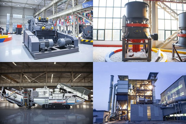
Discover whether bauxite crushers in Tanzania are the ideal choice for your crushing needs. Explore key features, advantages, and compare options, including SBM’s bauxite crushers Tanzania crusher for sale, tailored to optimize your bauxite processing operations.
View More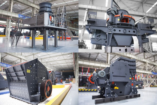
Discover the benefits of a mini crusher plant and learn key considerations for choosing the right machine crusher for sale. Explore how Sbm’s innovative solutions can meet your business needs efficiently and cost-effectively.
View More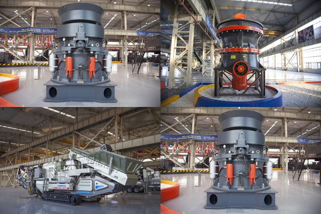
Discover where to find the best brick machine for sale in Africa. Explore leading manufacturers, essential features to consider, and top marketplaces to maximize your investment in high-quality brick-making machinery.
View More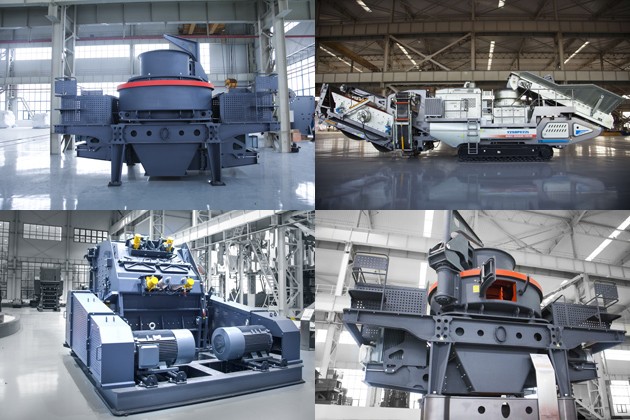
Discover the most reliable ball milling machine maker in our comprehensive article. We evaluate leading manufacturers, key features, customer reviews, and highlight SBM’s superior equipment for industrial applications. Optimize your milling processes today!
View MoreWe value your feedback! Please complete the form below so that we can tailor our services to your specific needs.


B6X Belt Conveyor adopts C-type steel as the main beam. It takes the modular structure and uses optimized headstock and tailstock. It is equipped with reversed V-type adjustable supporting legs. The whole machine is stable and compact and can be easily installed. It is an ideal upgrading and substitute product of traditional belt conveyor.
GET QUOTE