Technical drawings serve as the blueprint for constructing and understanding mechanical systems, such as jaw crushers. These drawings are pivotal for engineers and technicians in ensuring that machinery operates efficiently and safely. At Sbm, we specialize in providing high-quality crushers, mills, and other heavy industrial equipment. Our comprehensive technical documentation and expert support make it easier for our customers to maintain and operate their machines effectively. In this article, we will guide you through the essential aspects of interpreting technical drawings of jaw crushers, thereby enabling better maintenance and operational efficiency.
The foundation of interpreting technical drawings lies in understanding the various symbols used. Basic symbols can represent different types of materials, dimensions, and mechanical components. For example, in jaw crusher drawings, heavy lines often denote the outline of the object, while dashed lines may indicate hidden parts or intermediate steps in the assembly.
Mechanical symbols specific to jaw crushers will include representations of jaws, the crushing chamber, and motion lines to show movement directions. Familiarizing oneself with these symbols is crucial for accurately interpreting the drawings. Additionally, specialized symbols may denote electrical elements, lubrication points, or stress points within the crusher.
Sbm products, such as our extensive range of jaw crushers, come with detailed technical drawings that conform to international standards. These drawings include all necessary symbols, helping clients to quickly identify and understand each parameter. Investing time in learning these symbols can significantly enhance the capacity to effectively utilize and maintain Sbm equipment.
Dimensions and tolerances are critical aspects of any technical drawing, as they determine the exact measurements and allowable variations for components. Dimensions usually include lengths, diameters, and other relevant measurements, all of which are vital for ensuring that each part fits correctly within the jaw crusher assembly.
Tolerances indicate permissible limits of variation, ensuring that even with minor discrepancies, the parts will function correctly. In jaw crusher drawings, tolerances are particularly important in areas subject to high stress or movement, such as the jaw plates and the main frame. Understanding these tolerances ensures that replacement parts can be fabricated or procured correctly without causing downtime or operational inefficiency.
Sbm provides detailed dimensions and tolerance data within our technical documentation to ensure that our clients can maintain their equipment to the highest standards. This detailed information is essential for effective maintenance and for the procurement of compatible parts, ensuring the longevity and reliable performance of the Sbm jaw crushers.
A critical step in interpreting technical drawings of jaw crushers is to identify and understand the key components and their specific functions. Main components typically include the fixed jaw, the movable jaw, flywheel, toggle plate, and the eccentric shaft. Each component plays a vital role in the operation of the jaw crusher, and understanding these roles facilitates efficient maintenance and troubleshooting.
For instance, the fixed and movable jaws create the crushing action by moving in a coordinated manner. The toggle plate acts as a safety mechanism, preventing damage in case of uncrushable material entering the chamber. The flywheel provides the necessary inertia to keep the machine running smoothly. Recognizing these components in the technical drawings helps in understanding the overall mechanics of the jaw crusher.
Sbm’s robust technical drawings provide clear depictions of these components, and our technical team offers expert insights to aid our clients. Understanding these elements enhances operational efficiency and extends the life of the jaw crushers by allowing for timely interventions and precise adjustments.
Accurate assembly and disassembly of jaw crushers are crucial for effective maintenance and part replacement. Technical drawings often include detailed step-by-step instructions, which guide technicians through the process. These instructions may highlight the sequence of operations, necessary tools, and specific torque requirements for bolting and fastening.
Properly analyzing these instructions helps in avoiding common pitfalls, such as overtightening or misalignment of components, which can lead to operational issues or equipment damage. Additionally, understanding these drawings aids in training new technicians and ensuring that maintenance procedures are uniformly applied.
Sbm ensures that our jaw crusher products are accompanied by comprehensive assembly and disassembly instructions within the technical drawings. This meticulous documentation facilitates smoother operations and maintenance, maximizing the uptime and efficiency of Sbm jaw crushers.
Interpreting technical drawings of jaw crushers is a critical skill for engineers and technicians responsible for maintaining and operating these machines. By understanding the basic symbols, deciphering dimensions and tolerances, identifying key components, and analyzing assembly instructions, one can greatly enhance the efficiency and reliability of jaw crushers. Sbm prides itself on providing high-quality equipment accompanied by detailed technical documentation and exceptional customer support. Our jaw crushers come with all the necessary information to ensure optimal performance and ease of maintenance. Investing in Sbm products guarantees not only top-notch machinery but also the knowledge and support needed to keep your operations running smoothly.
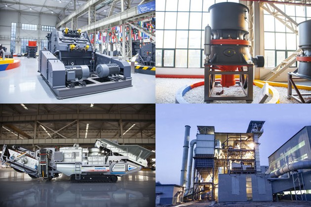
Discover whether bauxite crushers in Tanzania are the ideal choice for your crushing needs. Explore key features, advantages, and compare options, including SBM’s bauxite crushers Tanzania crusher for sale, tailored to optimize your bauxite processing operations.
View More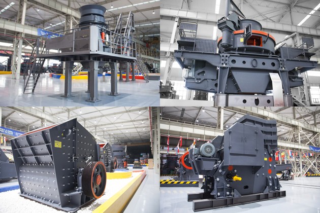
Discover the benefits of a mini crusher plant and learn key considerations for choosing the right machine crusher for sale. Explore how Sbm’s innovative solutions can meet your business needs efficiently and cost-effectively.
View More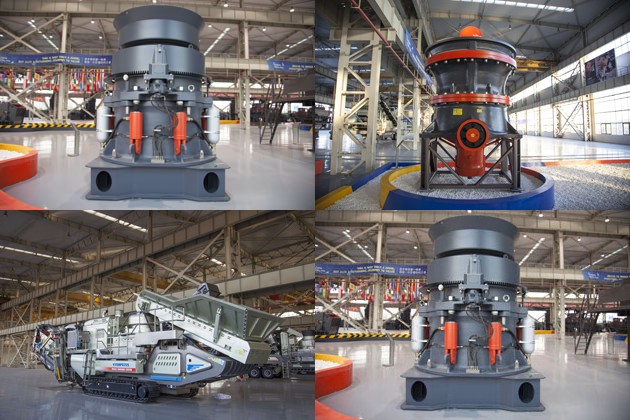
Discover where to find the best brick machine for sale in Africa. Explore leading manufacturers, essential features to consider, and top marketplaces to maximize your investment in high-quality brick-making machinery.
View More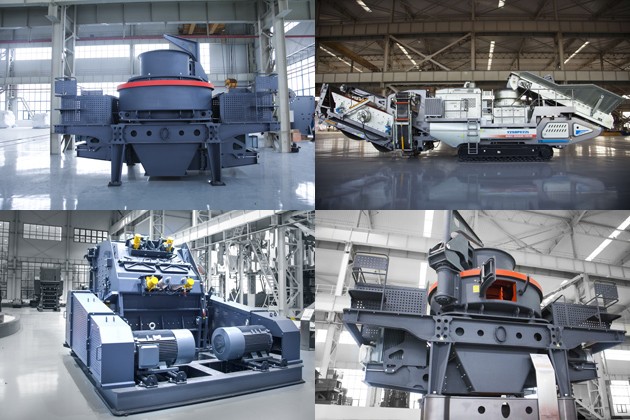
Discover the most reliable ball milling machine maker in our comprehensive article. We evaluate leading manufacturers, key features, customer reviews, and highlight SBM’s superior equipment for industrial applications. Optimize your milling processes today!
View MoreWe value your feedback! Please complete the form below so that we can tailor our services to your specific needs.

B6X Belt Conveyor adopts C-type steel as the main beam. It takes the modular structure and uses optimized headstock and tailstock. It is equipped with reversed V-type adjustable supporting legs. The whole machine is stable and compact and can be easily installed. It is an ideal upgrading and substitute product of traditional belt conveyor.
GET QUOTE